
PiLess BrewPi
Its no secret that temperature control is a huge aspect of brewing beer successfully. It can have dramatic side effects if you don’t keep the temperature in the yeasts range, or you may not be able to achieve flavors that you’re seeking from the yeast fermenting at a specific temperature. Now, in my past life as @dotps1, I covered in detail how to make a BrewPi. A temperature controller running with a Raspberry Pi and an Arduino board (that blog post can be found here, for now anyway, I’m not sure how long I will be keeping https://dotps1.github.io up). The BrewPi is defiantly a solid temperature controller solution, that allows for many customization, and the ability to create temperature profiles, allowing for temperature ramp up and cold crashing. And most importantly, it handles temperature swing. Unfortunately, the BrewPi is no longer officially supported on the Raspberry Pi/Arduino configuration, and as you can see the branch hasn’t been touched in years, https://github.com/BrewPi/brewpi-www/tree/legacy. I made this clear in my last walk through, which is over a year old now, and I had to fork the project and fix a bunch of dependency issues, that probably are already out of date.
Enter the PiLess BrewPi
So, theres another implementation of the BrewPi software out there, called BrewPiLess. And the best part is, it doesn’t need a Raspberry Pi, or even an Arduino Controller! And the project is actively developed, which means new features, and bug fixes. One of the really great features the BrewPiLess has, is that it supports logging data to BrewFather. There you can attach the device to a batch, and keep track of the temperature as the batch is fermenting, and all the data is stored in one place.
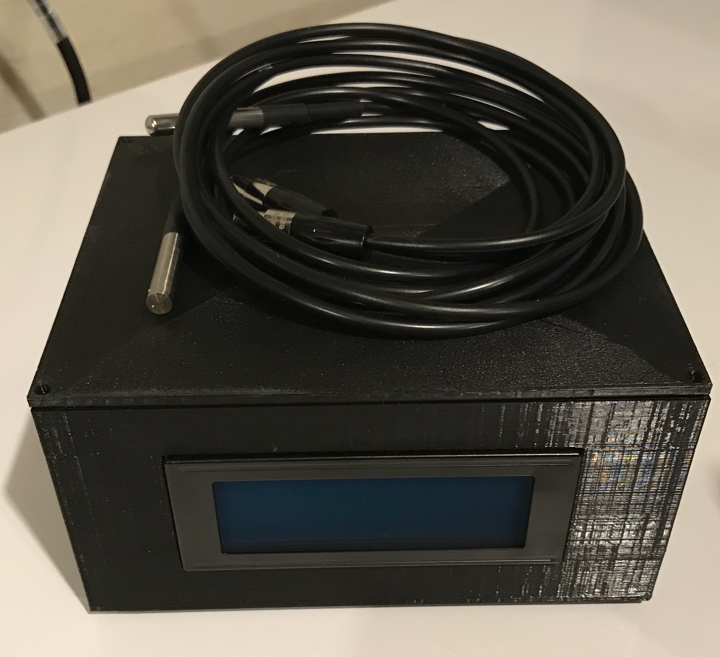
I was able to get this up and running, oh, I’d say about 10x faster then I got the BrewPi up. However, if you read my last blog on makeing a BrewPi, I housed everything in an outdoor sprinkler control box, it was huge and there where power cords and temperature probes hanging all over the place. Well this time, I wanted something fully modular, where all the cords where removable, and much much smaller. As small as absolutely possible. I reached my goal, but if you want your BPL exactly the same as mine, you will need to solder some connections in this build, and have access to a 3D Printer for the enclosure. These are not show stoppers, there is plenty of other ways to put everything together, this is just my way based on the things I regretted doing when I built my BrewPi, and features I wanted in this build.
Shopping List
Most of this stuff comes in bulk, so find a buddy that wants one too, and split the cost!
- ESP8266 NodeMCU (you don’t need two of these, but at that price, might as well, the second one is almost free)
- Two Channel Relay Module
- 20x4 LCD Module (this is optional if you would like a display on the controller)
- AC->DC 5V PSU (this acts a power supply unit inside the enclosure, powering all the componets, else you can power things with USB bricks, but that sounds like a mess)
- Mini XLR Male connectors (2 needed) (these are optional allowing for the temperature probes to be disconnected from the enclosure)
- Mini XLR Female connectors (2 needed) (these are optional allowing for the temperature probes to be disconnected from the enclosure)
- AC 3-Pin Outlets (2 needed)
- 3-Position Screw Terminal
- AC Rocker Switch
- DS18B20 Temperature Probes (2 needed)
- 4.7k Resistor (only 1 is needed, but good luck finding just 1 for sale)
- Breadboard Jumpers (really only need female jumpers for this project)
- Misc screws, wire, shrink tube, and wire nuts/connectors
Pro Tip
I am going to suggest starting this project by printing the enclosure. I am going to suggest this for a few reasons, first of all, most the customization I used in my build are only really needed if you are going to use my enclosure design. Things like the plugs, XLR connections, AC Rocker Switch and the LCD are all going to work perfect in my enclosure, Second, it takes a bit to print, and well, everything mounts in the enclosure, so you’re going to kinda need that part right away. If you’re not going to use my design, you can probably skip this part, and just mock everything up so you can figure out how your going to house this contraption.
The enclosure I designed is available on Thingiverse. It is one of the first things I’ve designed, so I’m sure there are things that could be done better but it works well enough for what it is. I’m not going to go into print settings for this as its out of the scope of this walk through. So, if you’re going this route, download the stl and get it printing because it will take a bit, you can print the lid while you are assembling the rest of the BPL.
Time to make the chimi-f***ing-changas
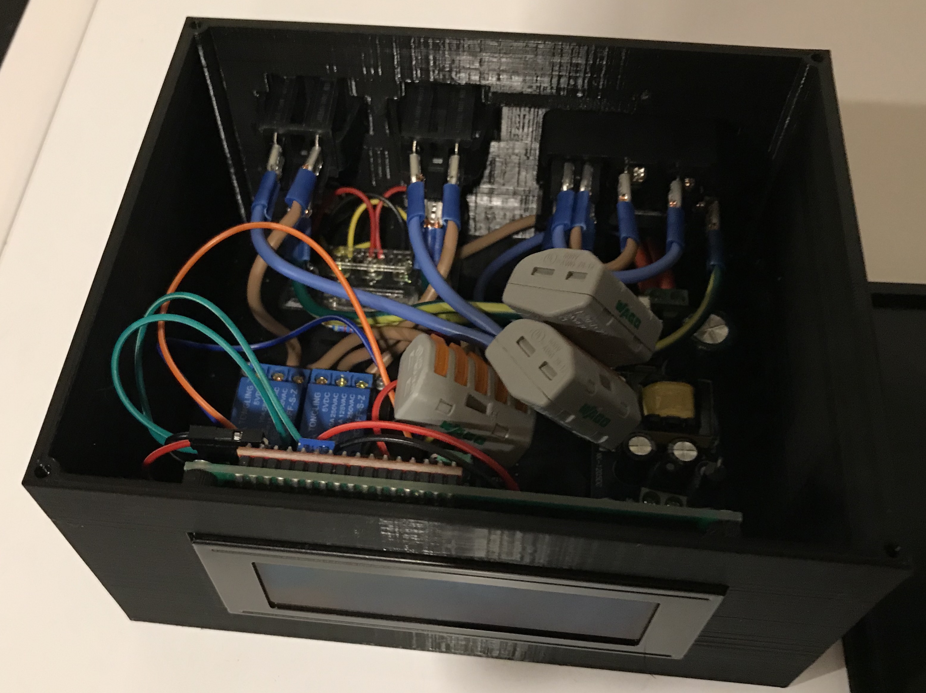
So, the first thing I want to say about this system, is that its dealing with 110v AC power, you will be running that power to the AC->DC converter (the NodeMCU and LCD run on DC power), and to the relay module, which essentially turns on/off your power outlets, which will control your Heating and Cooling in your fermentation chamber. I cannot over stress this enough, IF YOU ARE NOT COMFORTABLE WORKING WITH ELECTRICITY OR DON’T KNOW HOW BASIC ELECTRICAL WIRING WORKS, STOP WHAT YOU ARE DOING, PUT YOUR TOOLS DOWN, AND FIND SOMEONE WHO DOES! Ok, with that being said, lets get down to business.
Install the BrewPiLess bin on the ESP8266 NodeMCU
- Download the BrewPiLess Repository:
git clone https://github.com/vitotai/BrewPiLess.git
- If you don’t have it installed, you will need to download and install VSCode.
- Open the repository in VSCode. If you don’t have Platform.io installed, go to the extensions workspace and install it.
- On my mac, it failed to install the first, and it was because
virtualenvneeded to be installed. Completing the three steps listed in the Perquisites section here, and then uninstall/reinstall the extension fixed the issue.
- On my mac, it failed to install the first, and it was because
- Connect the NodeMCU to your computer via USB, and flash the bin to the board (make sure you are in the working directory of the repo):
command+shit+p>PlatformIO: Build>PlatformIO: Upload>PlatformIO: Clean
- After the flash is complete, the NodeMCU will begin broadcasting its own SSID, you need to connect to to this WiFi network to configure it to connect to your home WiFi.
- Username:
brewpiless - Password:
brewpiless - Open a browser it should auto connect to a config page, where you can change the username, password, and the title.
- Save the changes and on the next page enter you home wireless info.
- After this is complete you can connect back to your home wifi.
- Username:
Soldering
There are a few things to solder, and some need to be done before assembly:
- Solder your wires to the AC->DC 5V PSU, you won’t be able to do this after its in the enclosure.
- On the POWER IN side, you need 14-16 AWG wire, basically the same wire thats in the walls of your house, I clipped an old Molex computer cable and stole wire from that. This wire needs to be heavier gauge because it will have the 110v that is coming from your house to it, then will convert that to 5v DC.
- On the POWER OUT side, you need THREE Hot and Ground leads. These will power the NodeMCU, LCD and Relay. Just clip one end of the breadboard jumper wires for this.
- you can either solder the wire right to the board, or there is screw terminals that you could get as well, that you would solder to the board, and then you can screw the wires into the terminals, the choice is yours.
- The temperature probes need to be soldered to the female XLR connectors, the wire to pin layout don’t matter really, just as long as you do both of them the same.
- Unscrew the connector, put the plastic housing over the temperature probe wire, and solder the three wires from the probe to the three pin cups on the connector.
- Repeat this step for the other temperature probe.
- One thing I did was cut one probe a bit shorter then the other, for two reasons. First, the probe to monitor the fridge temperature didn’t need to be 6’ long. Second, it makes it easier for me to keep track of which probe is for the chamber temperature and which is for the beer temperature.
- While you have your solder gear out, might as well solder the wires to the male fittings as well.
- Sacrifice a few jumper wires for this, I would recommend using the same colors as the wires that where in the temperature probes so you can keep every thing lined up. The connectors are keyed so they can only go together one way.
- leave about 2-3 inches (cut a jumper in half) of wire, these will connect to the three position screw terminal that is directly behind the connectors in the enclosure (see the layout image below).
- Solder the wires to the pin cups, again, be sure your wire colors match up, your basically just making a pass thru connection in the enclosure, that is detachable if need be.
Assembly
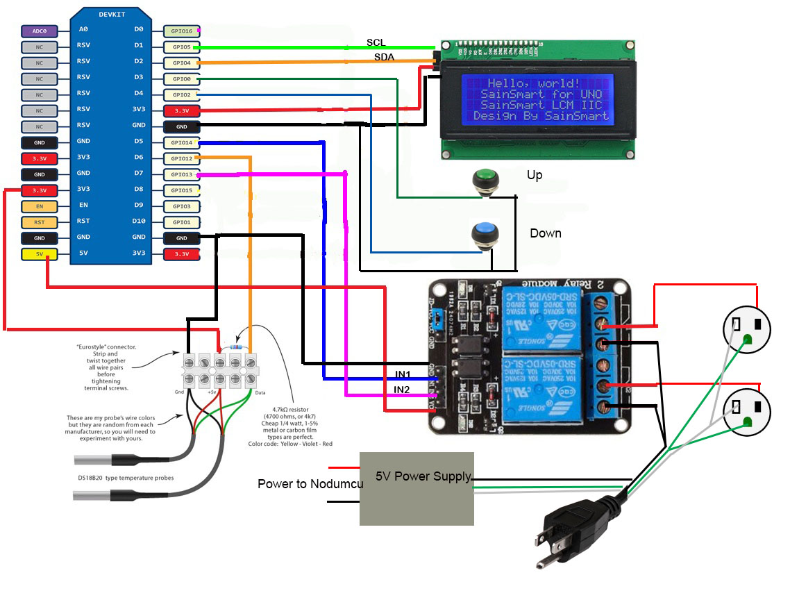
Wiring diagram:
 Layout diagram (I wasn’t able to find a 3D model of the AC-DC 5V PSU, that goes in with the Power IN facing way from the the LCD in the big empty space):
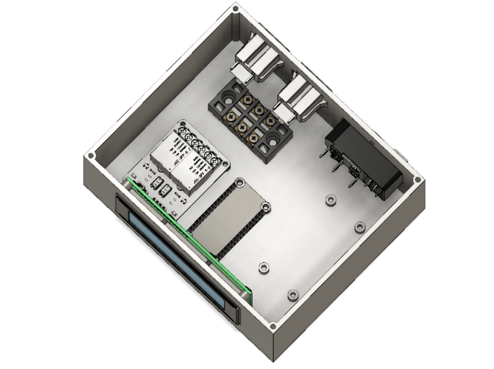
- At this point, you can start putting all the pieces in the enclosure.
- Place each board on its mounting posts, I used old computer motherboard screws to hold them down.
- The three position screw terminal I glued to the post.
- Use the diagram above to connect all the jumpers.
- The power for the NodeMCU will be supplied from the AC->DC 5V PSU to the 5V pin on the board.
- Connect a ground lead from the AC->DC 5V PSU to any ground on the NodeMCU board.
- In the diagram it shows the 5V pin is used to power the relay module, but that is assuming the NodeMCU is being powered VIA the USB port. Which is not the case, the 5V (maybe also labeled ‘Vin’) pin on the board will be used to power the NodeMCU itself, and then you can use one of the 3 power leads from the AC->DC 5V PSU to power the relay module.
- Be sure to add the resistor in the three position screw terminal when wiring in the temperature probes.
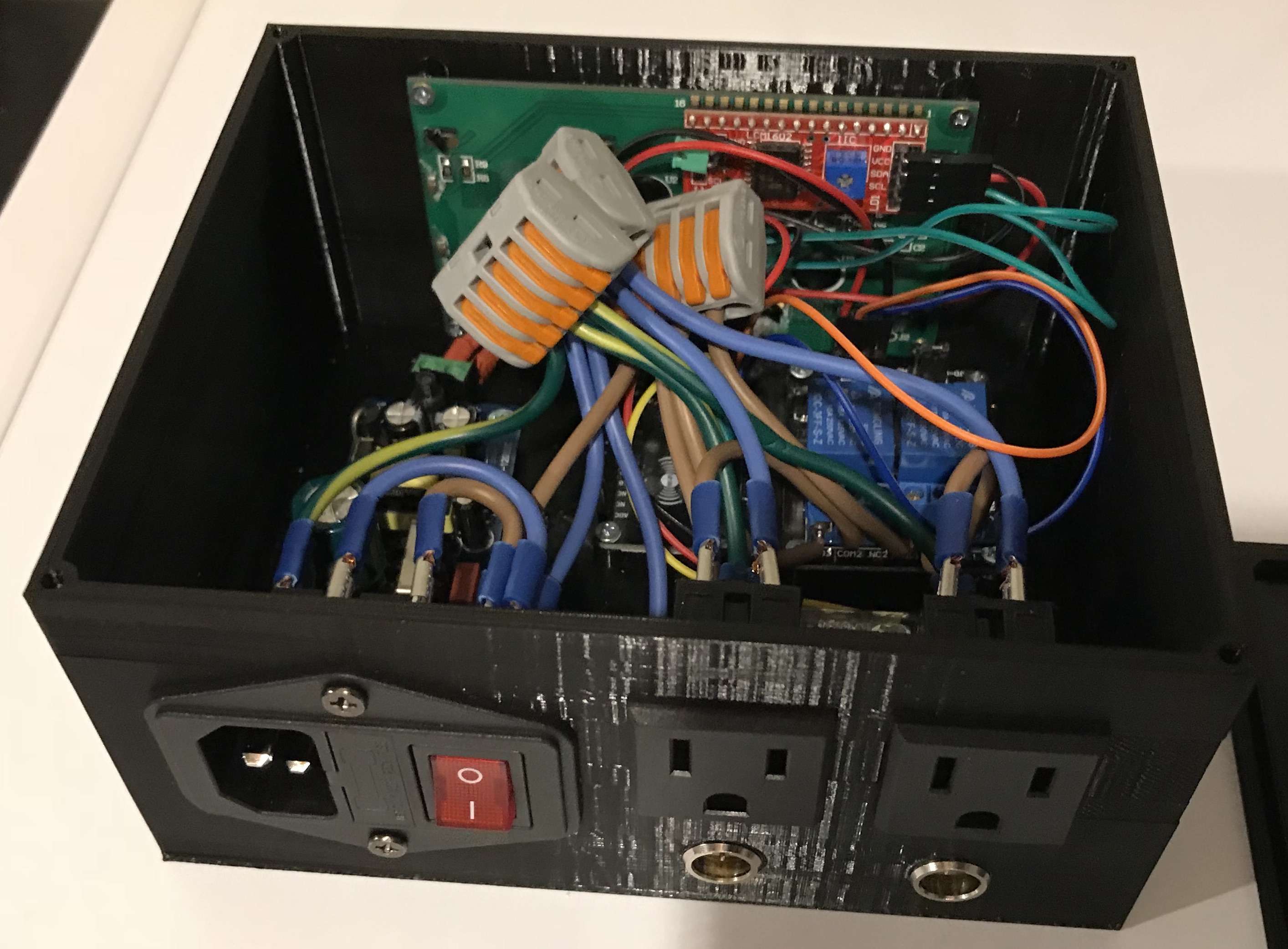
- Next wire in the power switch and the outlets.
- AC Rocker switch wiring digram:
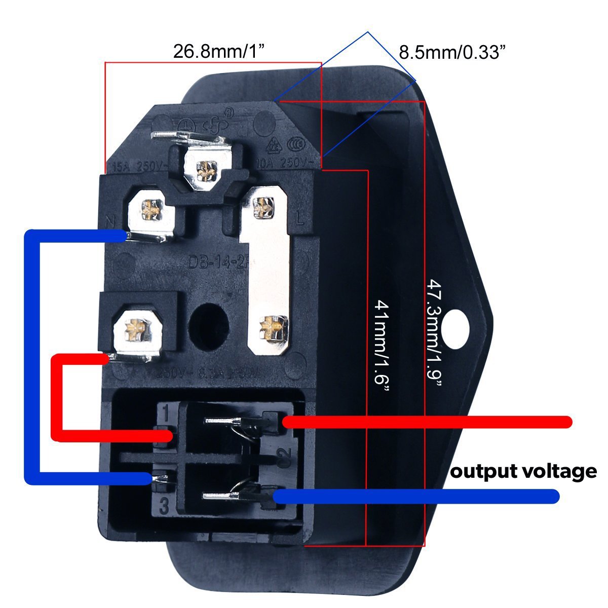
- From the power switch you will have three leads, 1 to the AC->DC 5V PSU, and 1 for each outlet. I used lever action wire nuts for this connection because there is 4 14AWG wires connecting at this point.
- The Relay acts as a switch to complete the circuit, so the hot goes in, and the back out to outlet, and the naturel goes directly to the outlet.
- AC Rocker switch wiring digram:
There really isn’t much more I can say about the wiring of this, all the information needed is in the diagram, there is more then one way to skin a cat, so just make sure your wiring is following the diagram and you’ll be fine. One thing to note, my fridge that I have plugged in the cooling outlet must draw a lot of amps, because the power switch comes with a 5 amp fuse, and when it turned on it, blew that, I had to replace it with a 10 amp fuse.
BrewPiLess Configuration
Once everything is up an running, there isn’t much left to do. Just need to set which plug is the hot and cold, and which probes are the chamber, and the beer.
- Connect to your BrewPiLess via a web browser at http://brewpiless.local (or whatever you named it in the setup screen.)
- Go to the
Device Setupscreen on the top right corner.- Be sure to click the
Erase EEPROMbutton at the top to be sure everything is reset. - Click
Refresh Device Liston the top load all your devices. - You have to manually select a
Deviceslot for each probe and plug, but these are arbitrary, they just have to be unique. - The temperature probes will have an
Addressvalue. - Setup 4 devices:
- Chamber Temp
- Beer Temp
- Chamber Heater
- Chamber Cooler
- I am not sure if there is a better way to then trial and error to identify which is which, for the probes you can just hold in your hand and the value will change on the display. For the plugs you will need to actually set a
BeerorFridgetemperature value and then one or the other will turn on.
- Be sure to click the
- Once your get everything setup, I would recommend backing up the configuration from the
Device Setupscreen incase you ever need to reload or rebuild, then you won’t have to play the guessing game on which device is which.
Extra Credit
If your like me, you are going to want to change the temperature units from C to F, because the NodeMCU has such little amount of space, there is no room for webpages to handle customization. Instead, you do it with commands:
- Navigate to http://brewpiless.local/testcmd.htm
- Issue this command:
j{"tempFormat":"F"}
- If your getting in the Kveik craze, and want to ferment hot AF, the you need to increase the
tempSetMaxvalue:j{"tempSetMax":"90.0"}
There is plenty of customizing you can do, just check out the BrewPiLess wiki: https://github.com/vitotai/BrewPiLess/wiki
Time for a Cold One
Whew, you did it! Nice work! Go pour yourself a cold one, I know I’m going too, sorry if I missed anything, this was a pretty intense walk through. Cheers!